Interrupt driven I/O is an alternative scheme dealing with I/O. Interrupt I/O is a way of controlling input/output activity whereby a peripheral or terminal that needs to make or receive a data transfer sends a signal. This will cause a program interrupt to be set. At a time appropriate to the priority level of the I/O interrupt. Relative to the total interrupt system, the processors enter an interrupt service routine. The function of the routine will depend upon the system of interrupt levels and priorities that is implemented in the processor. The interrupt technique requires more complex hardware and software, but makes far more efficient use of the computer’s time and capacities. Figure 2 shows the simple interrupt processing.
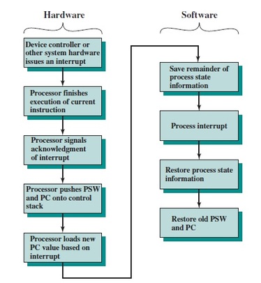
Figure 2: Simple Interrupt Processing
|
For input, the device interrupts the CPU when new data has arrived and is ready to be retrieved by the system processor. The actual actions to perform depend on whether the device uses I/O ports or memory mapping.
For output, the device delivers an interrupt either when it is ready to accept new data or to acknowledge a successful data transfer. Memory-mapped and DMA-capable devices usually generate interrupts to tell the system they are done with the buffer. Here the CPU works on its given tasks continuously. When an input is available, such as when someone types a key on the keyboard, then the CPU is interrupted from its work to take care of the input data. The CPU can work continuously on a task without checking the input devices, allowing the devices themselves to interrupt it as necessary.
|
|
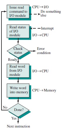
Basic Operations of Interrupt
|
|
- CPU issues read command.
- I/O module gets data from peripheral whilst CPU does other work.
- I/O module interrupts CPU.
- CPU requests data.
- I/O module transfers data.
|
Interrupt Processing
|
|
|
|
|
Advantages & Disadvantages of Interrupt Drive I/O
|
|
|
Advantages |
-
fast |
|
-
efficient |
|
|
Disadvantages |
-
can be tricky to write if using a low level language |
|
-
can be tough to get various pieces to work well together |
|
|
-
usually done by the hardware manufacturer / OS maker, e.g. Microsoft |
|
Design Issues
|
|
There are 2 main problems for interrupt I/O, which are:
- There are multiple I/O modules, how should the processor determine the device that issued the interrupt signal?
- How does the processor decide which module to process when multiple interrupts have occurred?
There are 4 main ways to counter these problems, which are:
- Multiple Interrupt Lines
- Software Poll
- Daisy Chain (Hardware Poll, Vectored)
- Bus Arbitration (Vectored)
These are known as the 4 general categories of techniques that are commonly used in I/O interrupt.
Multiple Interrupt Lines
As the name suggests, we provide multiple interrupt lines between the processor and the I/O modules. This allows multiple modules to be handled at the same time. However, it is not practical to assign many bus lines and processor pins to interrupt lines. One of the reasons is that there might be more than one I/O module attached to a single line. This defeats the purpose of this technique. The 3 techniques of the latter are usually used together with this technique to rectify its’ problems.
As the name suggests, we provide multiple interrupt lines between the processor and the I/O modules. This allows multiple modules to be handled at the same time. However, it is not practical to assign many bus lines and processor pins to interrupt lines. One of the reasons is that there might be more than one I/O module attached to a single line. This defeats the purpose of this technique. The 3 techniques of the latter are usually used together with this technique to rectify its’ problems.
Software Poll
Whenever an interrupt is detected by the processor, it branches to an interrupt service routine which will poll each and every I/O module to determine the exact interrupting module. The processor raises a poll which could be in the form of a command line. Consequently, the address of the respective I/O module which is interacted by the poll will be placed on the address line. The module will respond positively if it is responsible for setting the interrupt. On the other hand, every I/O module has an addressable status register. This register can be read by the processor to determine the interrupting module. After that, the processor is then branched to a specific device-service routine. The downside to this techniques is that it is time consuming.
Whenever an interrupt is detected by the processor, it branches to an interrupt service routine which will poll each and every I/O module to determine the exact interrupting module. The processor raises a poll which could be in the form of a command line. Consequently, the address of the respective I/O module which is interacted by the poll will be placed on the address line. The module will respond positively if it is responsible for setting the interrupt. On the other hand, every I/O module has an addressable status register. This register can be read by the processor to determine the interrupting module. After that, the processor is then branched to a specific device-service routine. The downside to this techniques is that it is time consuming.
Daisy Chain (Hardware Poll, Vectored)
This is actually a hardware poll. The interrupt acknowledge line is daisy chained to all the modules. Whenever there is an interrupt, the processor send out an interrupt acknowledge which will propagate throughout the series of I/O modules. This process will continue until it reaches a requesting module. The module will respond by placing a word on the data lines. The word is known as vector. This vector can either be the address of the module or a specific identifier. The processor subsequently directs the module to its’ specific device-service routine based on its’ vector. This technique is also known as the vectored interrupt. It completely removes the need for interrupt-service routine.
This is actually a hardware poll. The interrupt acknowledge line is daisy chained to all the modules. Whenever there is an interrupt, the processor send out an interrupt acknowledge which will propagate throughout the series of I/O modules. This process will continue until it reaches a requesting module. The module will respond by placing a word on the data lines. The word is known as vector. This vector can either be the address of the module or a specific identifier. The processor subsequently directs the module to its’ specific device-service routine based on its’ vector. This technique is also known as the vectored interrupt. It completely removes the need for interrupt-service routine.
Bus Arbitration (Vectored)
The last method which also utilizes vectored interrupts is bus arbitration. This method involves the I/O module gaining control over the bus before requesting for the interrupt. This is limited to only one module at a time. The processor sends an acknowledge signal whenever it detects an interrupt. The requesting module then places its’ vector on the data lines.
The last method which also utilizes vectored interrupts is bus arbitration. This method involves the I/O module gaining control over the bus before requesting for the interrupt. This is limited to only one module at a time. The processor sends an acknowledge signal whenever it detects an interrupt. The requesting module then places its’ vector on the data lines.
However, when there are multiple interrupts at a single time, there will be a need to assign priorities. These 4 methods have their own way of assigning priorities:
- Multiple Interrupt Lines: The processor picks the interrupt line with highest priority.
- Software Poll: The priority is determined by the order in which the modules are polled.
- Daisy Chain (Hardware Poll, Vectored): The priority is determined by the order in which the modules are polled.
- Bus Arbitration (Vectored): Employs a priority scheme.
|
Examples of Interrupt Structures
|
|
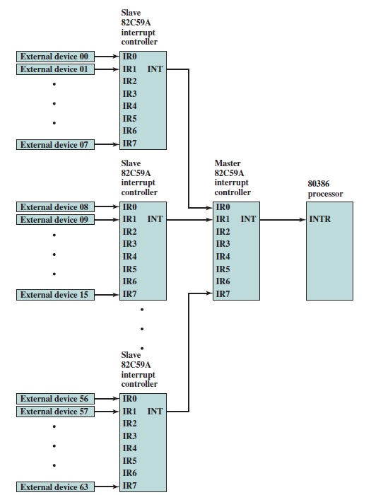
Intel 82C59A
Use of the 82C59A Interrupt Controller
- This is a type of interrupt controller/external interrupt arbiter.
- Main purpose is for managing interrupts, especially priorities.
- Contains an Interrupt Request (INTR) and Interrupt Acknowledge (INTA) line.
- Connects to external device and then to Intel 80386, allowing the handling of a variety of devices and priority structures.
- A single 82C59A can connect up to eight I/O modules.
- Can be arranged in cascaded arrangement for up to 64 modules.
- It has 3 modes:
- Fully nested: Interrupt request ordered based on priority.
- Rotating: Some applications have equal priority. Thus, a particular device has lowest priority in a group after being serviced.
- Special mask: Processor can inhibit interrupts from some devices.
Intel 82C55A Programmable Peripheral Interface
- This is an I/O module used for programmable I/O and interrupt-driven I/O along with 80386.
- In Figure 3, there are 24 I/O lines in the right hand side which are programmable by 80386 with the control register.
- The 24 lines are separated into three 8-bit groups (A, B and C). The C group can be further separated into two 4 bit-groups which can carry status and control signals.
- At the left hand side, there is an 8-bit data bus used to transfer control information to the control register.
- There are 2 address lines that specify 1 of the 3 I/O ports or the control register.
- A transfer can be done when CHIP SELECT line and the READ or WRITE line is enabled.
- The RESET line is used to initialize the module.
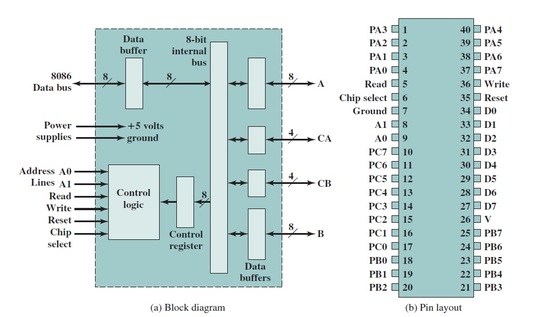
Figure 3: Intel 82C55A Programmable Peripheral Interface
|
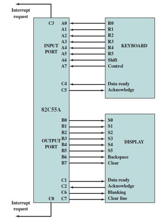
Figure 4: Keyboard/ Display Interface to 82C55A
|
